Flip flop circuit ic 4013 circuits diagram using make pinout set application homemade easiest projects reset clock simple practical seen Vhdl tutorial 16: design a d flip-flop using vhdl D flip flop logic diagram
JK Flip-flop: Positive Edge Triggered and Negative Edge-Triggered Flip-Flop
Praxe pilulka rytmus positive edge triggered d flip flop truth table Sr flip flop circuit diagram Edge triggered flip-flop circuit diagram
[diagram] logic diagram of d flip flop
D flip-flop[diagram] circuit diagram of d flip flop Circuit design – cmos implementation of d flip-flop – valuable tech notesFlip discrete flop circuit using transistors flops diagram hackaday explanation io.
What is a d flip-flop ??? (using discrete transistors)D flip flop logic diagram Bme(ec)403 module5 l39 d & t flip flops, truth table, state & timingTruth table of rs flip flop using nand gate.

D flip flop circuit diagram and truth table
Digital logic – d flip flop with asynchronous reset circuit designThe d flip-flop (quickstart tutorial) [diagram] logic diagram of d flip flopFlip flop vhdl circuit truth.
D flip-flopFlop logic schematic D flip flop circuit diagram and truth tableThe d flip-flop (quickstart tutorial).

D flip-flop and edge-triggered d flip-flop with circuit diagram and
7474 d flip flop pin configurationFlip flop Flip flop computer architecture sr input javatpoint organization clocked above figureHow to create a 4-bit register using d flip flop?.
Schematic of d flip-flop logic circuit.D flip flop [diagram] circuit diagram of d flip flopFlipflop: is it possible to create a circuit diagram for a d flip-flop.

Draw the logic symbol truth table and timing diagram of d flip flop
Jk flip-flop: positive edge triggered and negative edge-triggered flip-flopD flip flop circuit diagram and truth table D flip flop explained in detailFlip flop explained electronics general.
Make this easiest flip flop circuit using ic 4013T flip-flop explained .


d flip flop circuit diagram and truth table - Wiring Diagram and Schematics

Bme(Ec)403 Module5 L39 D & T Flip Flops, Truth Table, State & Timing

Circuit Design – CMOS Implementation of D Flip-Flop – Valuable Tech Notes

JK Flip-flop: Positive Edge Triggered and Negative Edge-Triggered Flip-Flop

The D Flip-Flop (Quickstart Tutorial)
VHDL Tutorial 16: Design a D flip-flop using VHDL

D Flip-Flop - Flip-Flops - Basics Electronics
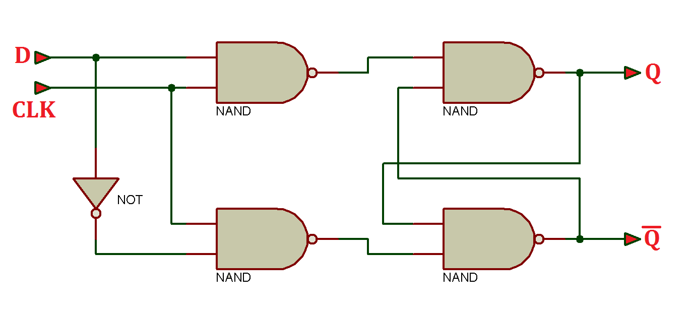
![[DIAGRAM] Logic Diagram Of D Flip Flop - MYDIAGRAM.ONLINE](https://i2.wp.com/circuitdigest.com/sites/default/files/inlineimages/D-flip-flop-circuit-representation-with-NAND-gates.png)
[DIAGRAM] Logic Diagram Of D Flip Flop - MYDIAGRAM.ONLINE